CAN bus cable assembly is a physical connection that is applied in Controller Area Network (CAN) systems. These systems are designed to facilitate communication between electronic devices in various applications, including the automotive and industrial sectors. The purpose to transmit data between devices on the network, enabling them to communicate with one another efficiently and reliably.
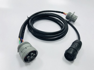
When selecting a CAN bus cable, carefully consider the data rate, cable length, and operating environment, Refer to the manufacturer’s specifications and recommendations to choose the right cable type that meets the needs of your particular CAN bus system.
There are a few main types of CAN bus cables which depends on the application, data speed, and network length.
Twisted Pair Cable– This is the most common CAN bus cable. It uses twisted pairs of wires (often 2 pairs) to help reduce interference. For better EMI interference. You can select the Shielded Twisted Pair (STP) Cable which has an additional shielding braid or foil around the twisted pairs. Common connectors used include DEUTSCH DTM connectors and Molex MicroFit connectors and M series circular connectors. 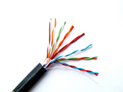
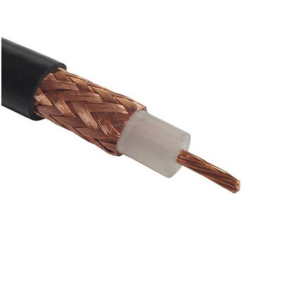
Coaxial cable, also called coax cable, is a type of cable that is sometimes used in high-speed Controller Area Network (CAN) bus applications. It consists of a single-core conductor surrounded by a grounded shielding braid, which helps to minimize electromagnetic interference (EMI) and signal loss. Common connectors include BNC connectors or aviation circular connectors.
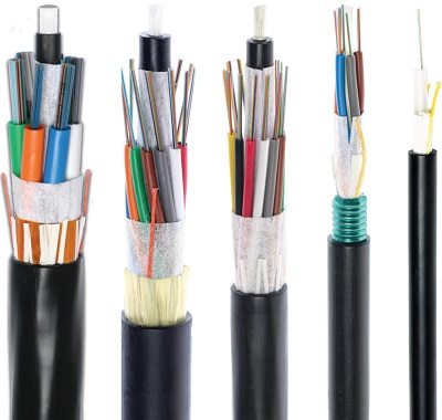
Optical fiber cable, also called fiber optic cable, is a type of cable that is immune to electrical interference and is commonly used to connect CAN nodes over longer distances. Fiber optic cable consists of thin strands of glass or plastic fibers that transmit data using light waves. This makes it an ideal choice for applications where high speeds and long distances are required. Fiber is connected using optical connectors such as CF8, ST, or custom terminals.
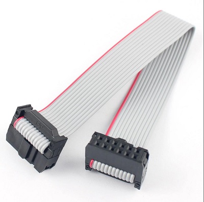
Flat Ribbon Cable-Ribbon cable is sometimes used within control units and ECUs. Connectors are typically custom multi-pin connectors or IDC socket connectors.
Here talk more details about connectors that are commonly used in a CAN bus system:
DB9 Connectors: These are 9 pin connectors, usually used for serial connections. They are often used in devices like CAN bus analyzers or interfaces for PCs.
OBD-II Connectors: Standard 16-pin connector type, These are typically used in automotive applications. An OBD2 (On-Board Diagnostics II) connector allows a device to interface with the diagnostic system in a car or other vehicle.
Terminal Blocks: These are often used in industrial applications where a secure, hard-wired connection is required. They allow for a direct connection to the CAN bus.
M12 Connectors: These are circular connectors that are often used in industrial and harsh environment applications because of their durability and resistance to dust and water.
D-Sub Connectors: These are robust and versatile connectors that come in a variety of pin counts, from 9 to 50. In CAN bus systems, the 9-pin version (DB9) is most common.
Aviation Connectors: Circular connectors designed for rugged use in aviation, like D38999/26 connectors, are sometimes used for CAN in aerospace applications.
CAN bus connectors are widely used in various industries, including:
Industrial automation:CAN is used in harsh environments for communication between devices like sensors, actuators, and controllers.
Automotive:Almost every modern vehicle has a CAN bus used for communication between the many microcontrollers involved in the vehicle’s operation.
Aviation:Some aircraft use CAN for communication between avionics devices.
Home automation:CAN can be used for communication between smart home devices.
Marine:CAN bus is used in some marine applications for communication between various onboard systems.
Can bus connectors provide a serial communication link with high noise immunity, They support real-time, high-speed (up to 1 Mbps) communication between electronic control units (ECUs) without a host computer.
How CAN bus system work in industrial control application:
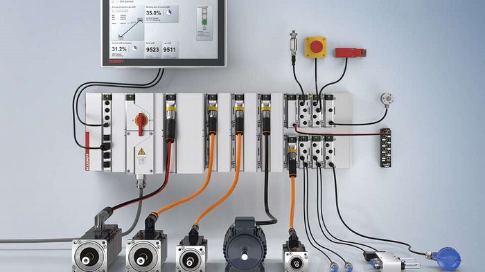
In the automation control system, there are several robotic arms that need to work together to assemble a product. The robotic arms are controlled by separate controllers. The robotic arm controllers need to communicate with each other to coordinate their motions and share sensor data. This is achieved using a CAN bus network.
Each robotic arm controller has a CAN bus interface. The controllers send messages containing information like current position, speed, acceleration etc. over the CAN bus to the other controllers. The CAN bus provides timely, reliable communication between the controllers with minimal wiring. This allows seamless collaboration between the robotic arms to optimize the assembly process.
In addition to the robotic arm controllers, sensors like force sensors on the robot grippers can also be connected to the CAN bus. Sensor data can be transmitted in real-time to the controllers. CAN bus network acts as a backbone allowing all the devices to share time-critical control data smoothly and efficiently. This increases speed and precision during the manufacturing process while reducing wiring complexity.
Additional devices like HMIs and data loggers can also be added to the CAN bus network to visualize or record data.
In the example, CAN bus is the ideal network to enable real-time communication and control between multiple devices in industrial automation systems. The noise immunity, speed, and priority-based messaging of the CAN bus provide the right capabilities for such demanding applications.
CAN bus is an essential communication protocol used extensively in industrial automation and control applications. The right choice of CAN bus connectors and cables is critical to creating a rugged, reliable, and high-performance network. Factors like data rate, cable length, and noise immunity need to be considered when selecting the appropriate cabling solution. Common connector types each have their own advantages based on the use case, from screw terminals for simplicity to aviation-grade circular connectors for extreme environments. Overall, the CAN bus enables real-time control,device interoperability, and reduced wiring in industrial systems. By understanding the varieties of CAN bus connectors and cables available, engineers can implement robust CAN networks that will perform reliably even in demanding industrial settings. With continued advancement in CAN bus technologies, we can expect its applications in automation and control to become even more diverse and business-critical.
If you’d like more information about Can bus cable/connector, please consult info@flexcontac.com


